The Role of HV Insulators in an ESP
HV insulators perform two primary functions, and in most ESP arrangements they perform both at once.
Electrical Isolation
They electrically isolate high-voltage components from the grounded ESP casing and supporting structures, holding the potential difference that the electrical field depends on.
Mechanical Support
Depending on the design, certain insulators also support electrode systems or transmit mechanical movement while maintaining electrical isolation.
Because the insulator carries both duties, a cracked, contaminated or incorrectly fitted unit is not only an electrical problem — it can also be a mechanical one.
Isolation path — schematic, not to scale
Three configurations, three different duties.
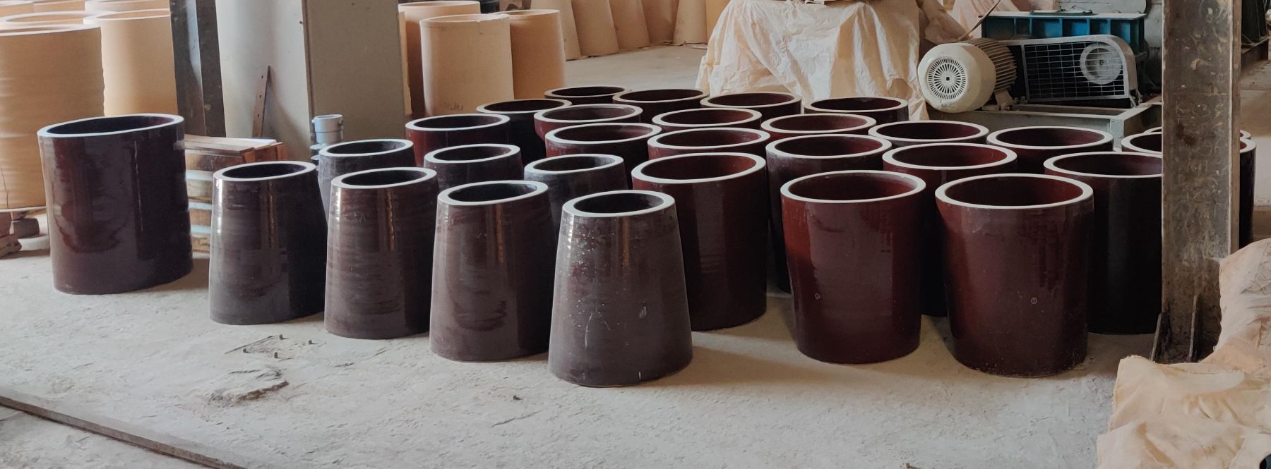
Hollow Ceramic Support Insulator
High-Voltage Support & Isolation for ESP Electrode Systems
The hollow ceramic support insulator is used as a high-voltage insulating and sealing component associated with the discharge-electrode suspension arrangement where it enters the electrical field. The suspension rod passes through the central bore, so the insulator holds the electrical break at the same point where the mechanical load is carried.
Depending on the ESP configuration, the insulator can also provide mechanical support to the discharge-electrode system, and its interface area forms part of the seal between the gas space and the insulator housing.
The glazed external surface matters as much as the body: surface condition governs how readily dust and moisture establish a leakage path across the insulator.
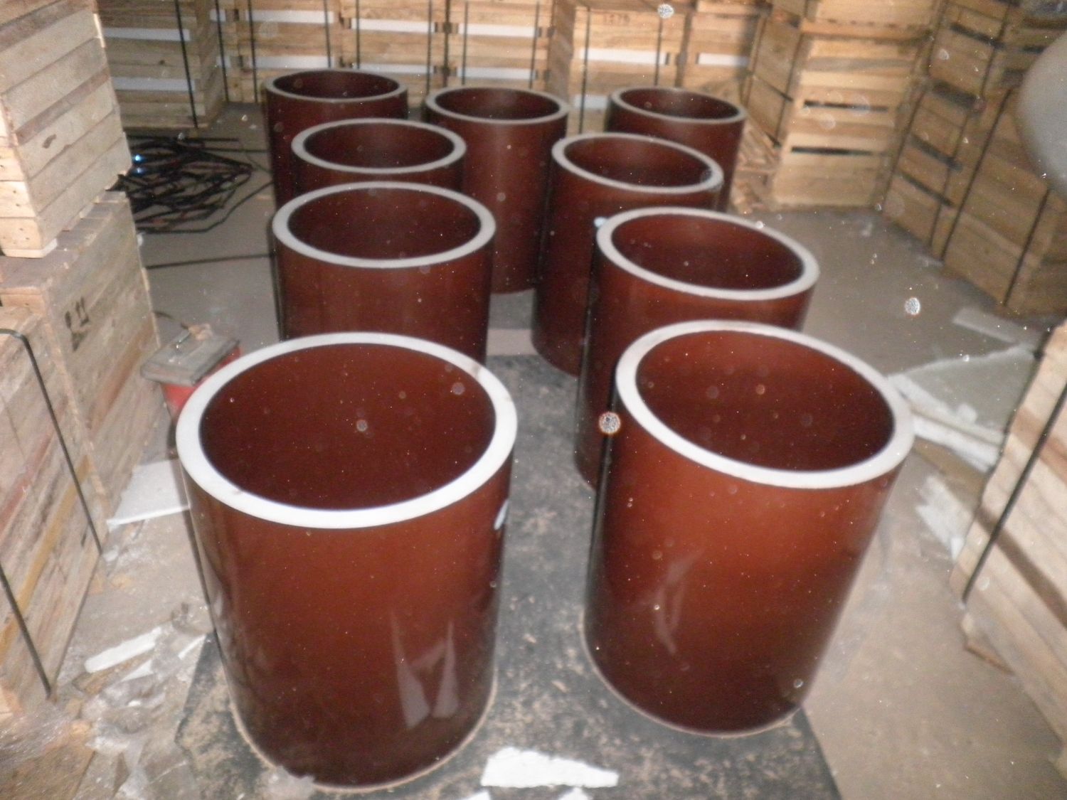
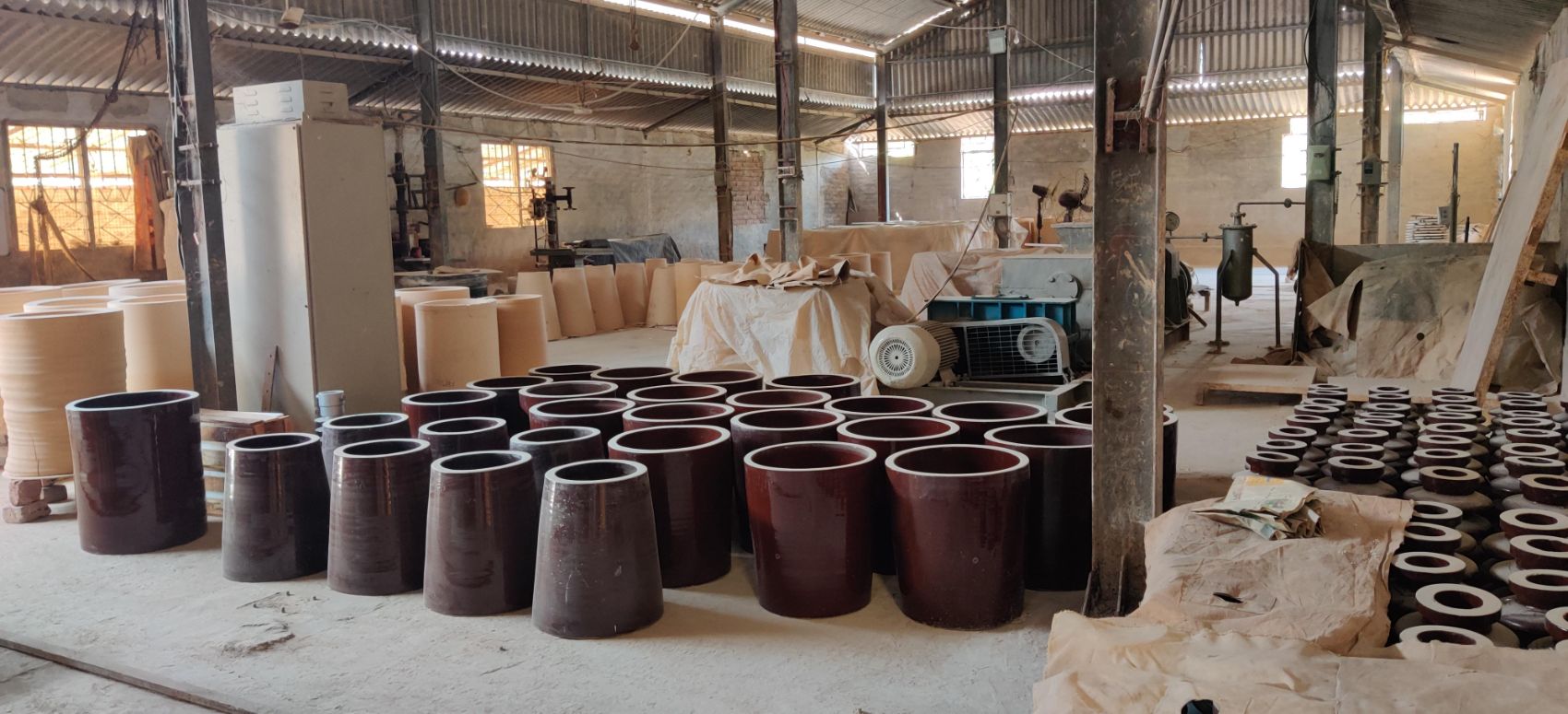
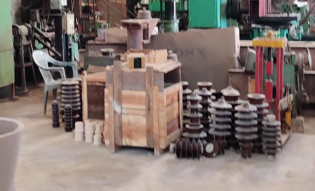
Hollow ceramic support insulators at the works
Representative Configurations
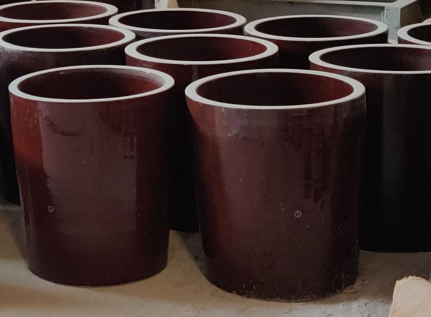
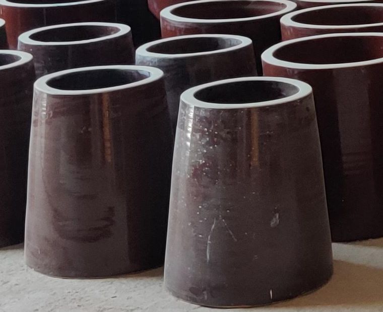
Cylindrical and conical configurations shown. Typical ESP configurations — subject to customer/OEM design.
Hollow Insulator — Sectional Arrangement
ESP Post Insulators
Rigid High-Voltage Support & Electrical Isolation
Post insulators provide high-voltage insulation while mechanically supporting the associated ESP high-voltage assembly. The construction is a ceramic body with metal fittings at each end — one interfacing with the HV assembly, the other with the grounded support structure.
Unlike the hollow insulator, there is no central bore carrying a rod: the post carries the load through its own body in compression, so the mounting arrangement at both fittings determines how the load is distributed.
Where the arrangement is exposed to dust deposition, the shed profile and creepage path along the body are selected against the location rather than assumed.
Ceramic grade, binder system and fitting metallurgy are selected according to application and customer/OEM requirements.
Section view — schematic, no dimensions
ESP Shaft Insulators
Mechanical Power Transmission with High-Voltage Isolation
The shaft insulator is installed between the rapping shaft located inside the electrical field and the external drive / gear-motor arrangement. Its purpose is to allow mechanical rotation and power transmission while maintaining the required electrical insulation between the high-voltage discharge-electrode system and the grounded ESP casing.
It is the one insulator in the ESP that has to do two things which normally conflict: pass torque continuously, and block a high potential difference across the same short length. That makes both the ceramic body and the coupling interfaces at each end critical — a loose or worn coupling shows up as shaft misalignment and, eventually, as a cracked body.
Torque passes continuously from the drive to the rapping mechanism while the ceramic body holds the potential difference across the casing wall. Torque, speed and voltage values are as per ESP design and customer/OEM specification.
Which insulator does what.
Exact configuration and application depend on the ESP/OEM design.
Four insulating duties inside one precipitator.
ESP insulators serve a dual function: providing mechanical structural support within the precipitation chamber while electrically isolating the high-voltage DC electrode circuit from the grounded metal outer casing. They do it under harsh conditions — immense mechanical loads, volatile temperature swings and corrosive, dust-laden gas.
Support Insulators — Suspension / Post
Rigidly hold and suspend the weight of the discharge electrode framework while keeping it isolated from the grounded casing. Typically installed atop the ESP roof inside penthouse enclosures, with compartment heaters to prevent conductive moisture or ash condensation.
Shaft Insulators — Rapping / Drive
Transmit rotational mechanical force from external motors to the internal rapping system, connecting the external drive to the tumbling hammer shafts and enduring continuous torsional stress and vibration as hammers strike the plates.
Wall Bushings — Feed-Through
Guide high-voltage DC bus-bars or power cables through the grounded outer walls of the ESP penthouse or transformer-rectifier enclosure.
Damping Resistance Insulators
Integrated within the high-voltage secondary circuit to isolate and absorb electrical harmonic peaks and surge anomalies generated by the TR set.
Types 01 and 02 are covered as products above. Types 03 and 04 are shown for completeness of the ESP insulation picture — availability is subject to enquiry.
Shape follows creepage distance and load path.
Form factor design prioritises maximising the electrical creepage distance — the shortest path along the insulator surface — to prevent flashover, while maintaining the structural load threshold.
Nearly all form factors feature exterior sheds or skirts — the corrugations that break direct tracking paths along the surface.
Selected against the location, not from a shelf.
ESP HV insulators are built around a ceramic / porcelain insulating body with metallic fittings bonded or assembled at the interface area. Material grade and specification are selected according to application and customer/OEM requirements.
The selection is driven by where the insulator sits and what it has to survive there.
Insulator Fittings & Assemblies
ESP insulators may be supplied with appropriate metallic end fittings, mounting components and interfaces according to the application — as a bare ceramic body, or as a complete assembly ready to install.
Fitting metallurgy and bonding method are as per product specification and customer/OEM requirements.
Ceramic bodies, classified by duty.
Reference classification for ESP insulating bodies. Material grade and specification for any given supply are selected according to application and customer/OEM requirements.
High-Alumina Porcelain
Up to 90–95% aluminium oxide. The general standard where high mechanical strength and thermal shock resistance are both required.
Alumina-Silicate / Mullite
For stable high-temperature operation under standard continuous mechanical load.
Above 95% Al₂O₃
For heavy metallurgical or waste-incineration duty where temperatures exceed 400 °C, and against sudden boiler start-up thermal shock.
Low-Dielectric-Loss Ceramic
Formulated for high-voltage DC profiles, to limit leakage current under dirty operating conditions.
Glaze Treatment
Finished with a high-temperature brown or white silicate glaze, giving the smooth, dust-repellent surface that keeps the creepage path clean.
Material groups per IEC 60672 classification.
Typical ranges for ESP insulator duty.
The figures below are industry reference ranges for ESP insulator applications, given so that engineers can frame an enquiry against the right order of magnitude.
These are reference values for the application, not published ratings for a specific supply. Rated values for any insulator supplied are confirmed against the ESP design and the customer/OEM specification.
Specification frame.
Values are defined per enquiry against the ESP design and the existing component. No representative numbers are published here.
Selecting the Right ESP Insulator
Selection is a sequence, not a single choice. Each step narrows the configuration.
Replacement HV Insulators for Existing ESPs
Damaged, cracked, contaminated or incorrectly fitted insulators can compromise the electrical isolation and mechanical reliability of an ESP. Aeon Tech Solutions supports replacement requirements for existing installations based on available drawings, photographs, dimensions, samples and OEM information.
Don't Know the Exact Insulator Specification?
Share a photograph of the existing insulator along with available dimensions, nameplate information, drawing or ESP/OEM details. Our technical team can review the requirement and identify the information needed for a suitable replacement.
Potential inspection points.
Inspection and testing requirements can be defined according to product specification and customer requirements.
Typical ESP Applications
ESP HV Insulators — Product Gallery
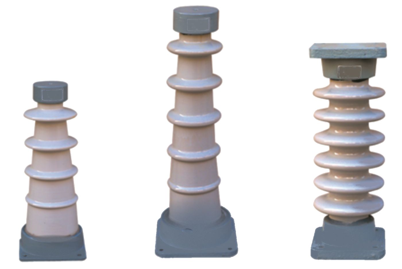
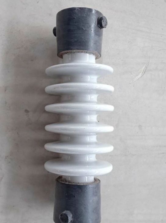
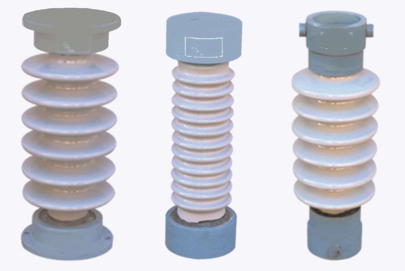
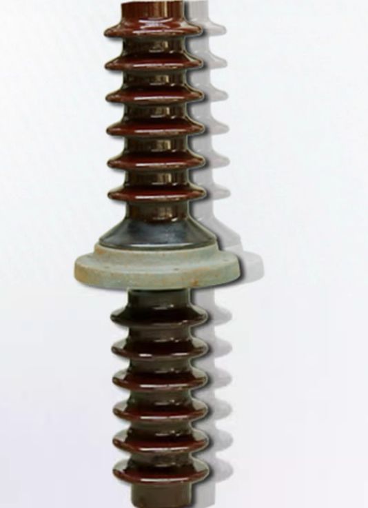
Representative outlines and dimension callouts.
Dimensions shown for illustration. Actual dimensions are as per product specification / customer / OEM drawing.
Insulation supplied against the ESP, not a catalogue.
ESP-Specific Application Knowledge
Designed around the requirements of electrostatic precipitators.
Multiple Insulator Configurations
Hollow, post and shaft arrangements.
Replacement Support
Suitable for maintenance and replacement requirements.
Drawing-Based Supply
Can be evaluated from customer/OEM drawings.
Sample-Based Identification
Existing component photographs and dimensions can be used for technical evaluation.
Application-Specific Solutions
Configuration based on electrical and mechanical requirements.
Request an HV Insulator Quote
A photograph and a few dimensions are usually enough to start. Where a parameter depends on the ESP/OEM design, leave it blank and we will come back on it.
A photograph of the existing insulator in situ, plus the OEM drawing if you have it.