The set, and the intelligence driving it.
An ESP field is energised by a high-voltage DC supply. The TR set produces it; the controller decides — many times a second — how hard to push before the gap flashes over. Replace one without considering the other and the gain is usually smaller than expected.
We work with equipment from established ESP power suppliers, including KraftPowercon and Ador Powertron platforms, and support existing installations of both.
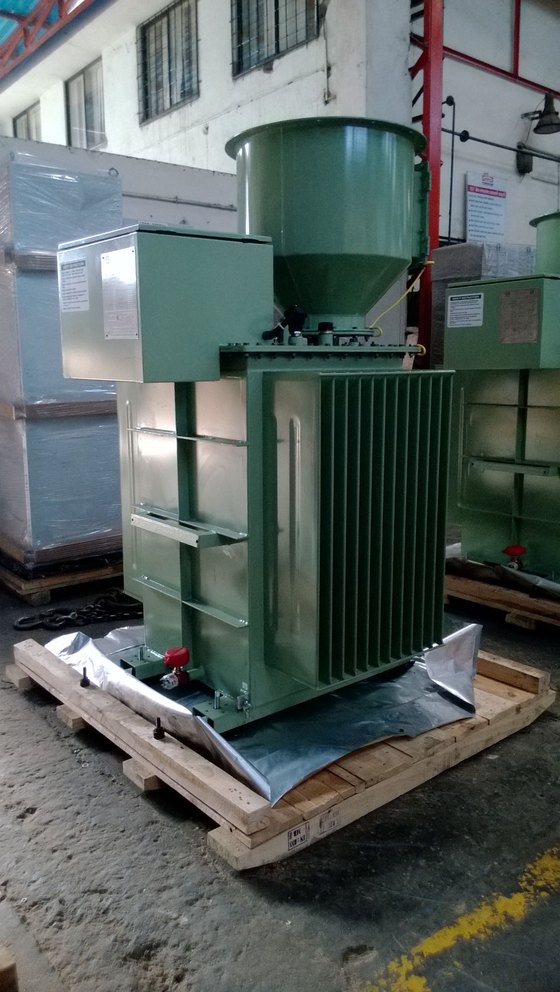
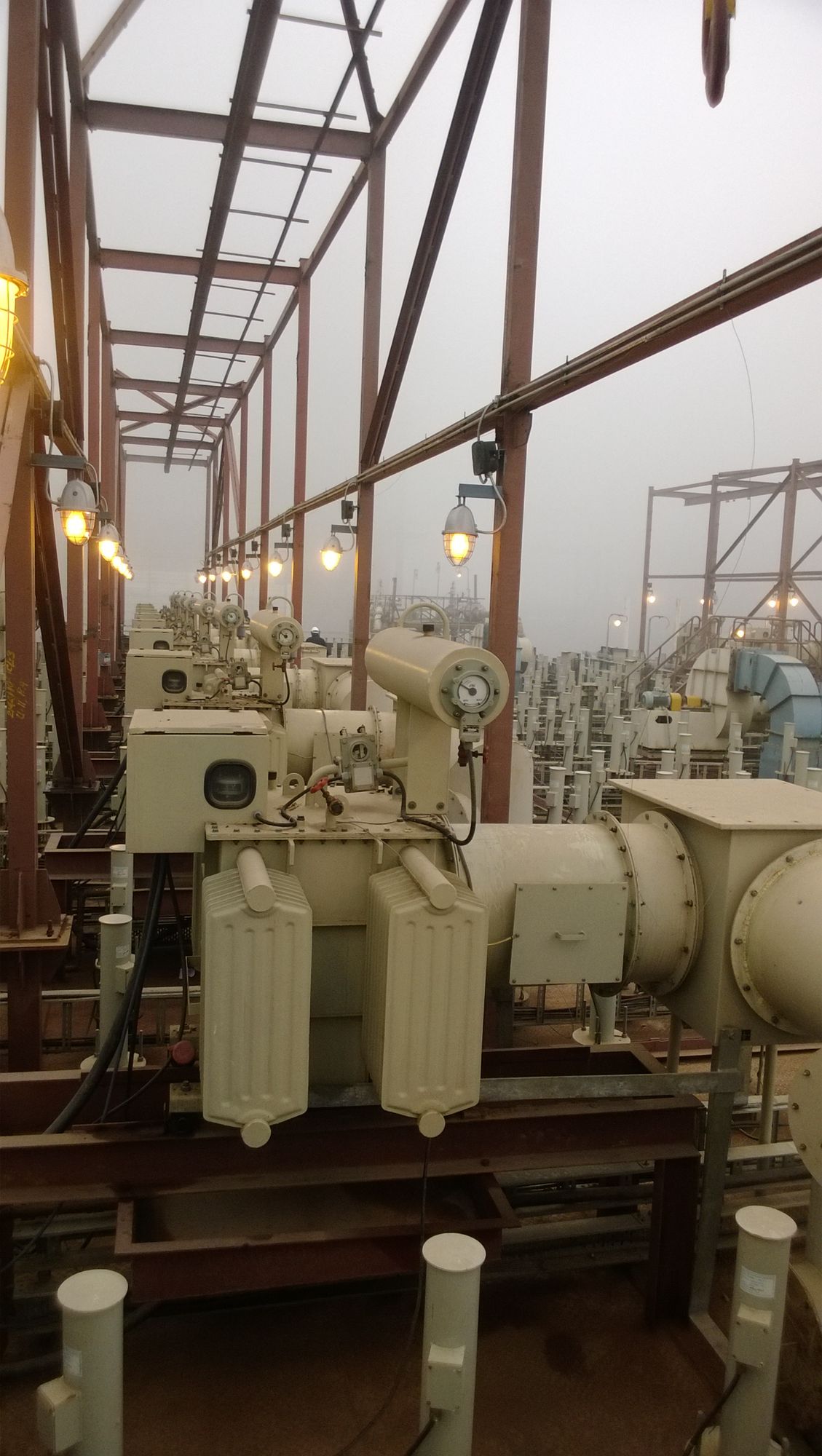
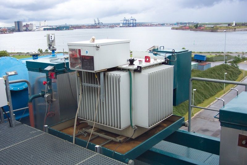
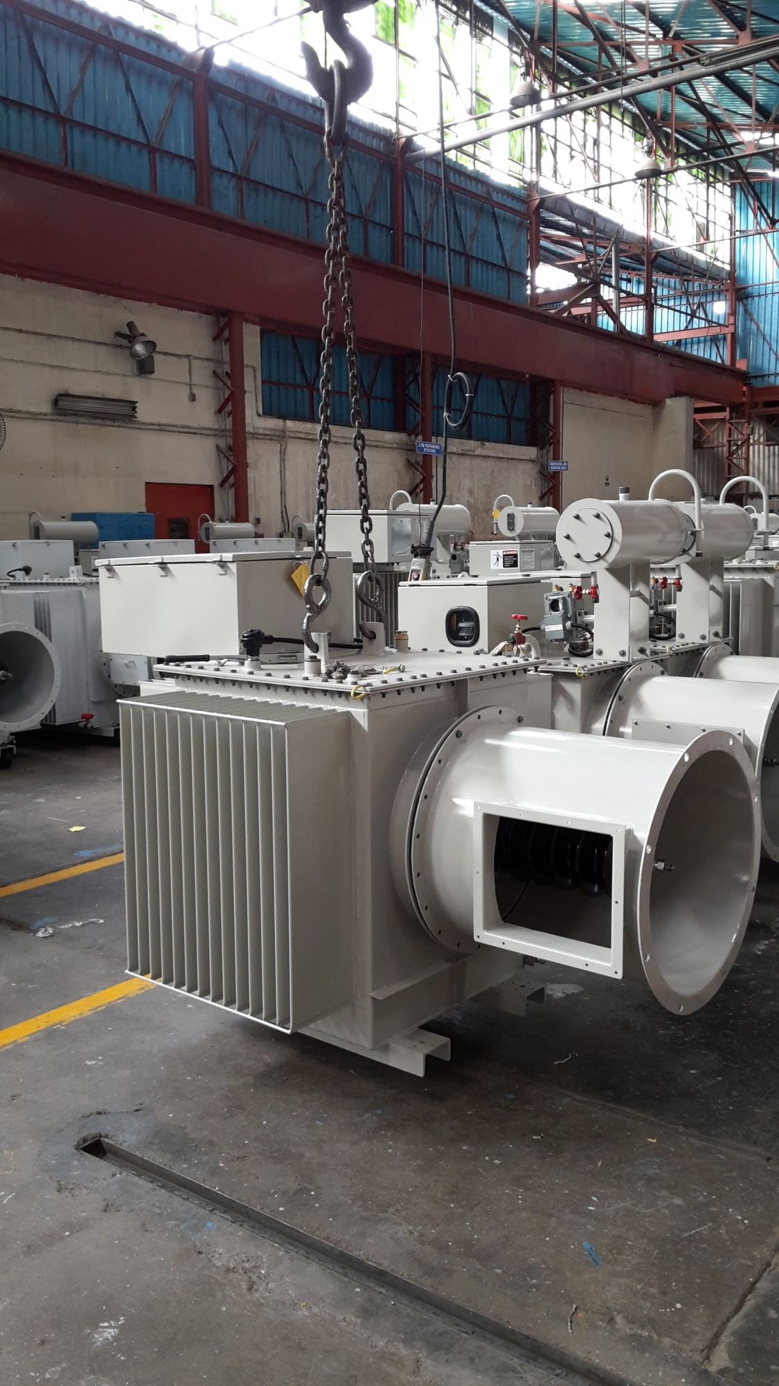
HV Transformer Rectifier Sets
Three energisation technologies, chosen against the field, the dust and what the plant needs to achieve. All three are supplied for new installation, like-for-like replacement and retrofit onto existing fields.
Supplied With
Control Cabinets & Controllers
The controller is the cheapest place to buy ESP performance. A current-generation controller on a sound TR set will often recover more than a mechanical overhaul, because it can push the field closer to flashover and recover from a spark faster.
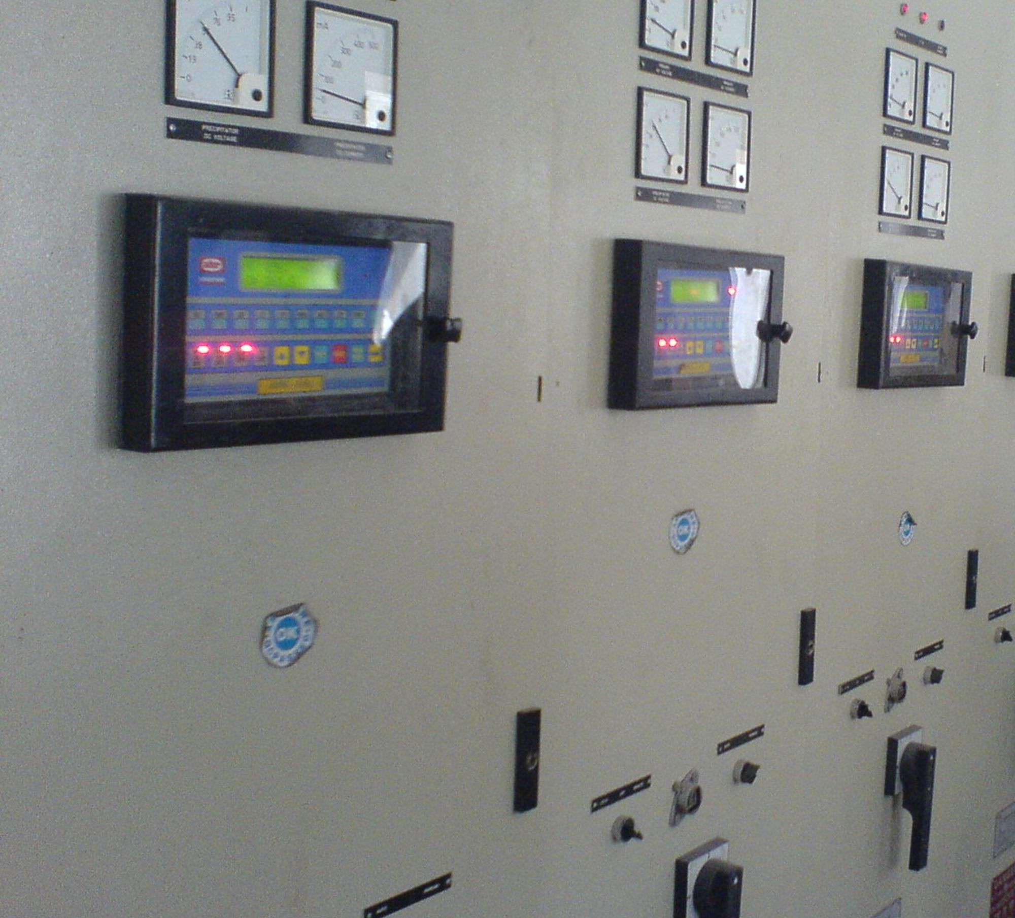
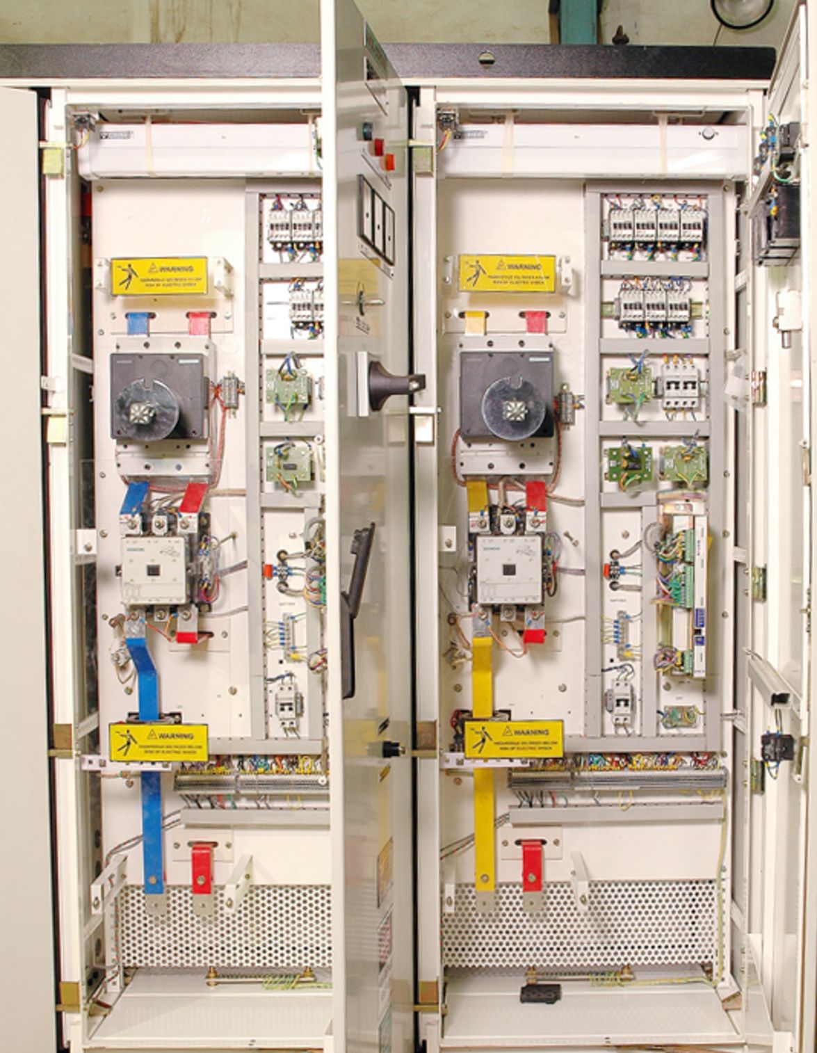
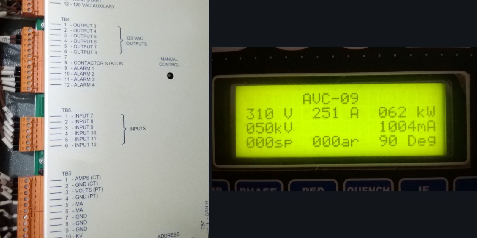
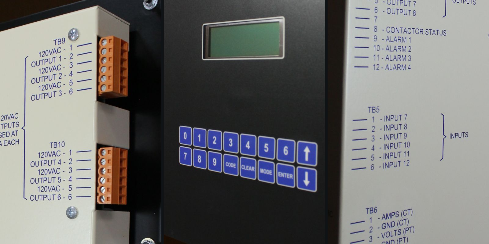
Control Functions Typically Available
Available functions depend on the controller platform selected. Confirmed against the datasheet for the specific model at quotation stage.
Existing TR sets in sound condition can usually be kept. Where the controller generation is obsolete and spares have dried up, an upgrade kit onto a current platform is normally the shortest route back to full field voltage.
Discuss a Retrofit →Three energisation technologies, three different arguments.
The choice between single phase, three phase and high frequency energisation is not a question of which is newest. It follows the field, the dust resistivity, the incoming supply and what the plant is trying to achieve.
Conventional Thyristor-Controlled TR Sets
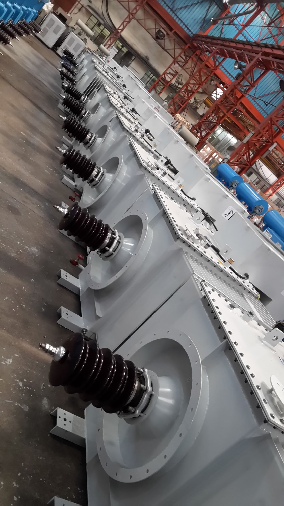
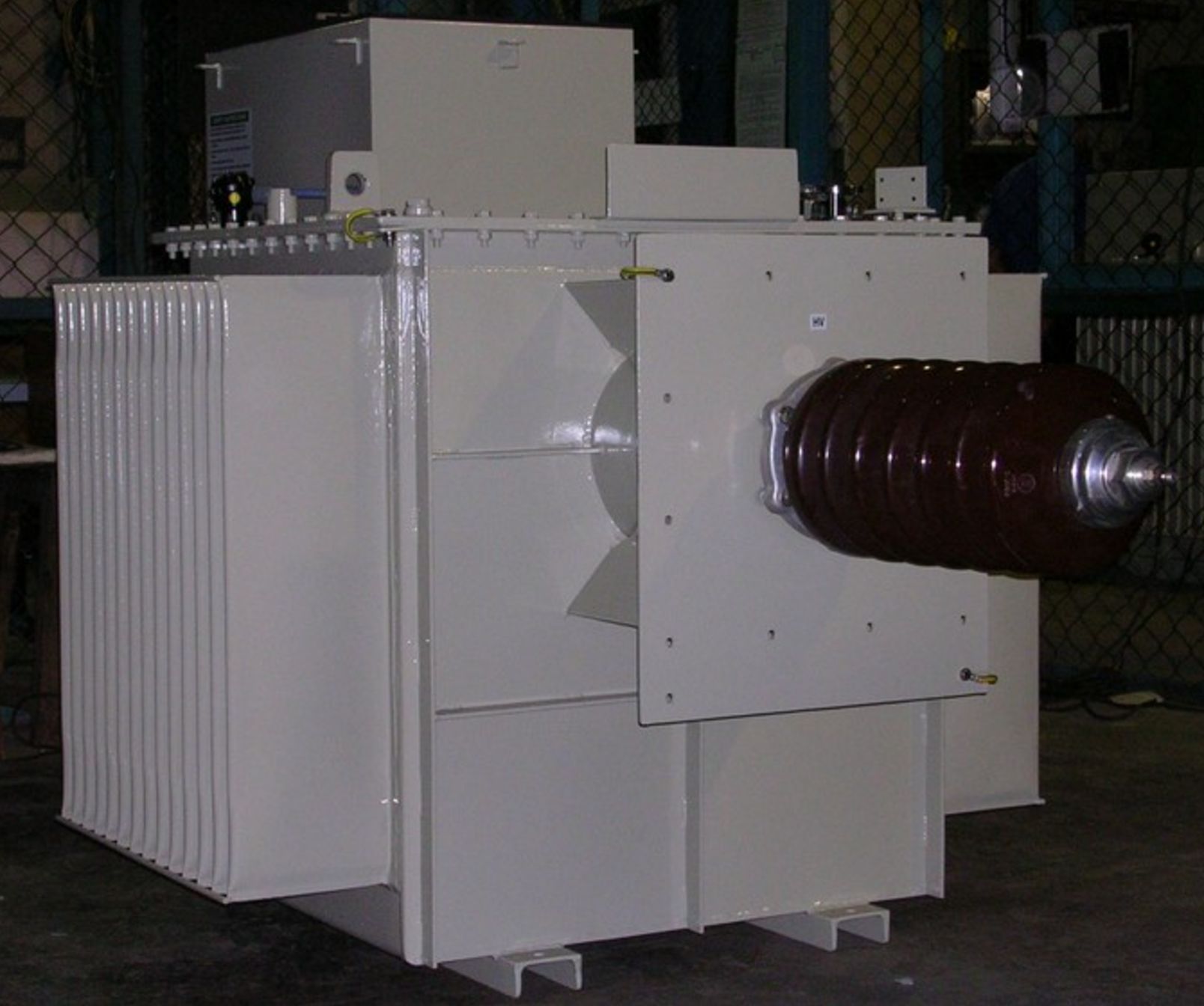
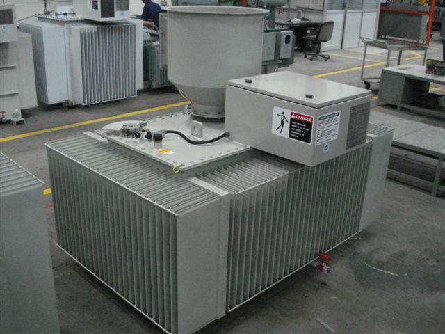
A single phase thyristor AC controller feeds the primary of a step-up transformer; the secondary output is rectified by a high-voltage bridge and delivered to the field through the HT bushing. The whole assembly sits in an oil-filled tank that serves as both insulating medium and cooling path, with a conservator to accommodate thermal expansion.
Because conduction is controlled by phase angle on a 50 Hz supply, the DC delivered to the field carries substantial ripple. Peak voltage — not average — sets the sparking threshold, so ripple directly limits the average voltage the field can hold.
This is the arrangement the majority of installed ESPs were built around, and it remains entirely serviceable. Where the tank, bushing and windings are sound, the sensible intervention is usually the controller rather than the set.
Characteristics
Where it fits
Like-for-like replacement of a failed set, or new supply where the field arrangement and control philosophy are already fixed.
Three Phase TR Sets
All three phases of the incoming supply are controlled and rectified, so the field sees six pulses per cycle instead of two. The DC waveform is markedly smoother, which raises the average voltage achievable before the peak reaches the sparking threshold — more corona power into the same field for the same spark rate.
The load presented to the incoming supply is symmetrical, which matters on sites where a bank of single phase sets has created persistent phase imbalance.
The set remains an oil-filled transformer, so the mechanical and maintenance picture is familiar — it is the electrical behaviour that changes, not the maintenance regime.
Characteristics
Where it fits
Larger fields, sites with unbalanced incoming supply, and cases where a higher average field voltage is the stated objective.
High Frequency Switch Mode Power Supplies
The incoming supply is rectified to a DC link, then inverted at kilohertz frequencies through a compact high-frequency transformer and rectifier. Because the switching frequency is orders of magnitude above 50 Hz, the output is near-constant DC with very little ripple, and the transformer itself is a fraction of the size and weight of an equivalent oil-filled set.
Two consequences matter operationally. Almost the full peak voltage becomes useful average voltage. And spark response is measured in microseconds rather than milliseconds — the supply can quench and re-establish the field between mains half-cycles, so a spark costs far less collection time.
The same speed makes intermittent and pulsed energisation genuinely controllable, which is what makes high frequency effective on high-resistivity dust where back-corona limits conventional sets. Units are typically dry, sealed and roof-mountable, removing oil handling from the maintenance picture.
Characteristics
Where it fits
Emission-limit-driven upgrades, high-resistivity dust and back-corona problems, weight-constrained roofs, and retrofits where removing oil from the roof is itself an objective.
High-tension switches — isolation, earthing and safe access.
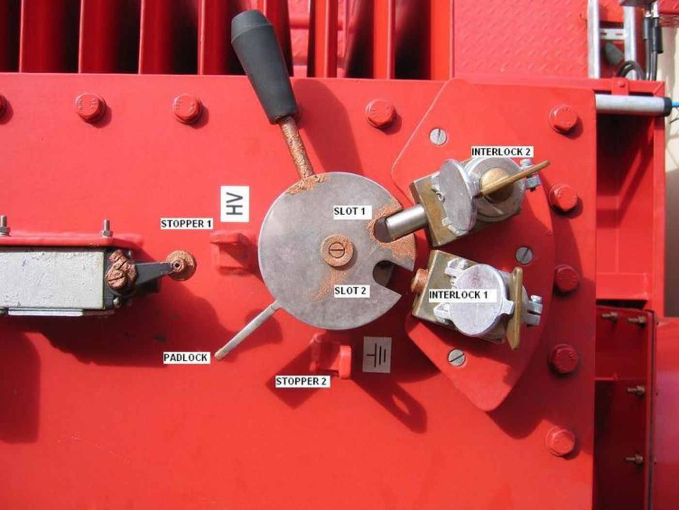
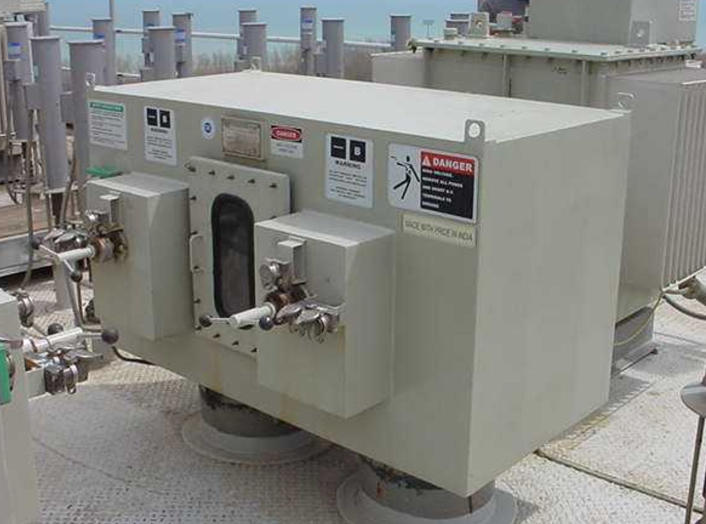
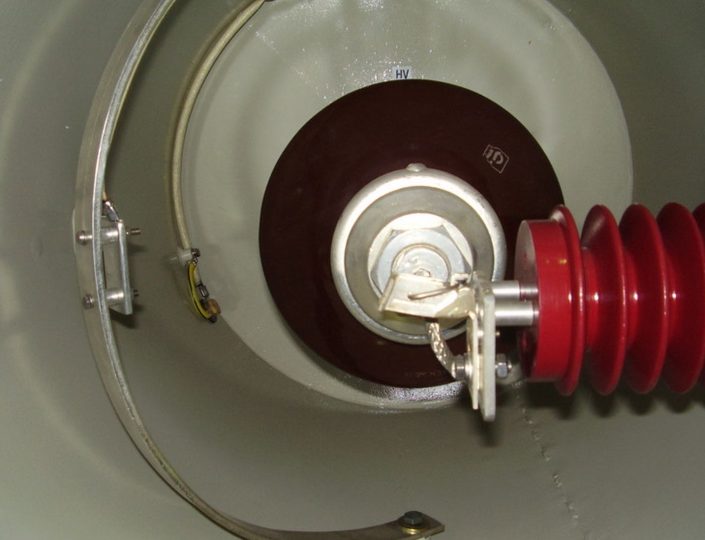
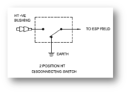
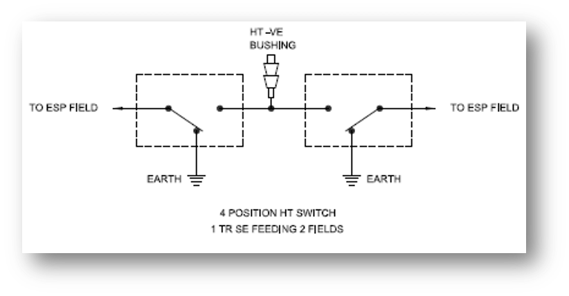
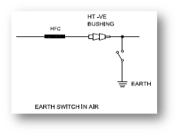
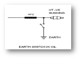
An HT switch sits between the TR set output and the ESP field. It performs two duties: selecting or isolating a field for maintenance, and positively earthing the high-voltage system before anyone enters the precipitator. On an ESP that second duty is the one that matters most — the field retains charge after the set is switched off.
Field Isolation
Disconnects an individual field from its TR set so work can proceed on one field while the remaining fields stay in service.
Positive Earthing
Connects the HV system solidly to earth and holds it there, discharging residual charge in the field before internal access.
Mechanical Interlocking
Key or castell interlocks make the earthed position a precondition of access, so the sequence cannot be defeated by procedure alone.
Enclosure & Insulation
Sheet steel enclosure with insulated support of the HV path, viewing window on the switch position, and cable or busbar entry to suit the installation.
Switches & Spares
Complete HT switch units, and spares for existing switches — contacts, insulators, operating mechanism, interlock hardware and position indication.
Rated to the Installation
Voltage rating, number of ways, interlock scheme and enclosure arrangement are confirmed against the TR set output and the plant's access procedure.
Replace the part that has failed, not the set that hasn't.
A TR set is rarely beyond use as a whole. In most cases the tank, windings and core are sound and the fault sits in a bushing, a rectifier stack, a protection device or a feedback card. Identifying which is the difference between a component replacement in a shutdown window and a capital replacement.
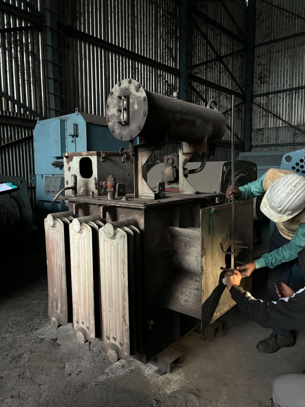
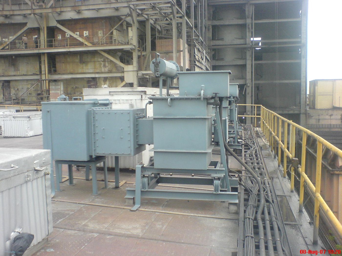
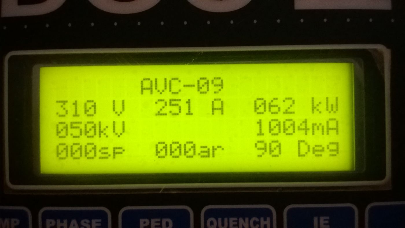
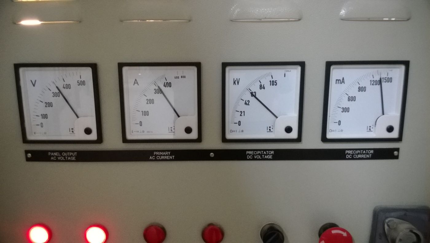
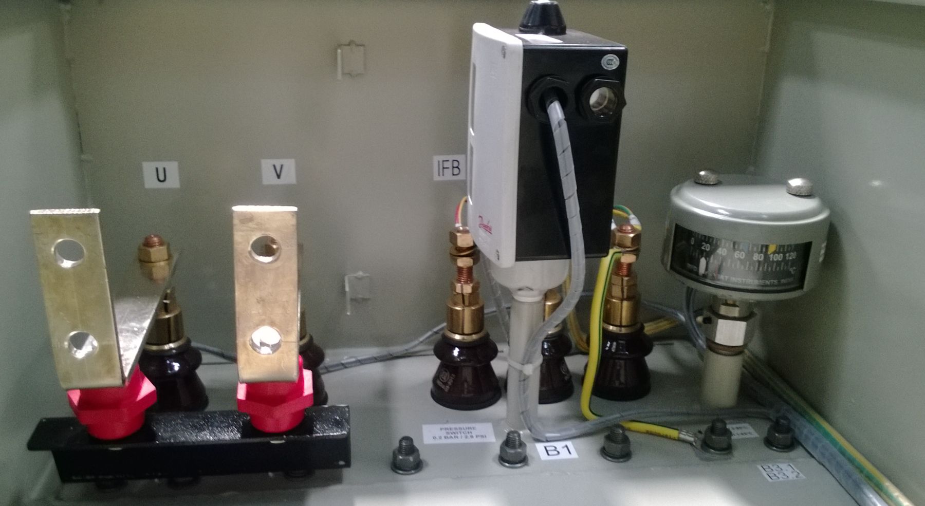
Spare support for existing TR set & control panel installations
Supplied individually or as a scope defined against an inspection. Ratings are confirmed against the existing set.
HT Bushing (36 kV / 52 kV)
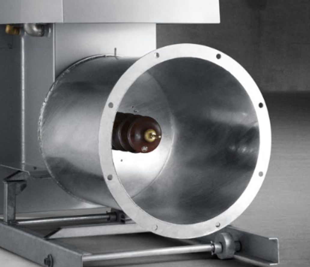
Carries the rectified high-voltage output from inside the oil-filled tank to the field connection. Tracking, cracking or oil seepage at the bushing is one of the most common reasons a serviceable set is taken out of use.
Rectifier Stack
The high-voltage silicon diode assembly that converts the transformer secondary output to DC. A partially failed stack shows as reduced secondary voltage and a distorted V–I characteristic rather than an outright trip.
Pressure Switch
Protection device monitoring tank pressure and responding to the rapid rise produced by an internal fault. Supplied as a direct replacement where the existing device has failed or become unreliable.
Dial Thermometer
Oil temperature indication with alarm and trip contacts. Loss of reliable temperature indication removes the earliest warning of a set being worked beyond its thermal capability.
Voltage Feedback Card
Conditions the secondary voltage signal from the set for the controller. A drifting card causes the controller to regulate against a false reading — the field appears healthy while running below its capability.
Current Feedback Card
Conditions the secondary current signal for the controller and its spark detection logic. Faults here typically present as erratic spark counting or premature current limiting.
LT Bushing
Carries the transformer primary connections through the tank wall. Replaced where the porcelain is damaged or the seal has begun to weep at the flange.
Thyristor
The power semiconductor in the primary AC controller. Supplied to match the existing stack rating, with the gate lead and heatsink arrangement of the panel it replaces.
Firing Card
Generates the gate pulses that set the thyristor conduction angle. Degraded firing shows as unstable primary current and an inability to hold the set at its operating point.
Pressure Release Valve
Relieves tank pressure on an internal fault and reseats afterwards. Supplied as a direct replacement where the existing valve has seized, corroded or begun to weep oil.
Rated against your field, not a shelf.
TR set rating follows the field area, the dust resistivity and the V–I characteristic the field can actually sustain. Send the existing nameplate and, if you have it, a V–I curve — that pair answers most of the sizing question.
Send Nameplate Details →Request a TR Set or Controller Quote
The existing TR set nameplate photograph and the controller make and model are usually enough to start. Everything else can follow.
Prefer to send it directly? Email salesats@aeontechsolutions.com or message us on WhatsApp.